Föhrenbach Expert Insights.
Flexible Circuits
Flex Foil Circuits
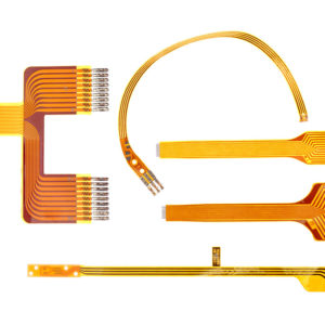
FFCs are flexible flat cables containing tinned or bare copper conductors, laminated between two high-quality insulating foils. In most cases, a minimum width of 0.28 mm is recommended for the conductors. Common conductor thicknesses are 35 µm, 50 µm, 76 µm, 100 µm, 125 µm and 200 µm. The pitch is standard between 1.27 mm and 2.54 mm. Depending on the application polyethylene terephthalate (PET) and polyethylene naphthalate (PEN) of varying thicknesses are used for the insulating foils.

Flex Printed Circuits
FPCs are printed circuits. The conductors are applied to an insulating foil using a photochemical or screen printing process. The minimum conductor width is 100 µm and they can be tinned to improve solderability. Common conductor thicknesses are 18 µm, 35 µm, 50 µm, 71 µm and 105 µm. Depending on the application, polyimide (PI), polyethylene terephthalate (PET) and polyethylene naphthalate (PEN) are used for the insulating foils. The thicknesses are variable but in general they are between 25 µm and 100 µm.
FPCs have two major advantages:
- Their design philosophy is similar to classic printed circuits, so electronic and mechanical components can be mounted on them.
- They are not restricted to specific forms. They can de punched or cut-out by a special process using laser technology.

Crimping
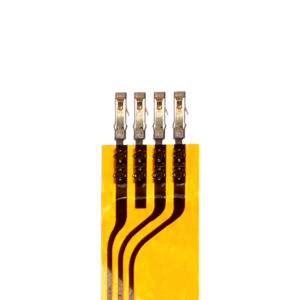
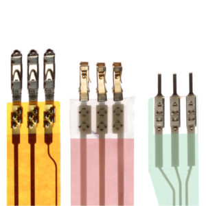
Crimping is a two-step connector application process, which makes it very different from clinching. First, the contacts are detached from a carrier strip and crimped one by one onto the foil. In the second step, the connector is slid over the contacts on the foil. Popular contact types are MQS, nano MQS, AMPMODU (.100 & .050) Crimpflex, Duflex, StarCrimp, MTS to name just but a few. Pitches often used are 1.27 mm, 1.8 mm and 2.54 mm. Crimp-contact geometry is extremely important to achieve reliable crimping results. Each contact is different, and therefore we have developed matching crimp-contact geometries for each manufacturer and type.

Clinching
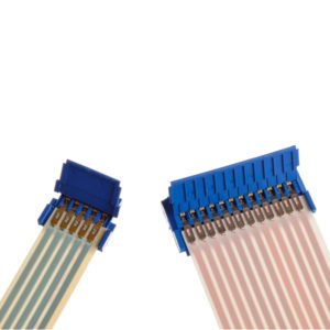
Contrary to crimping, contacts are pre-assembled in an insulating connector housing before the clinching process takes place. During clinching, the foil is slid into the connector and then all contacts are simultaneously clinched. Amphenol ICC clincher connectors with up to 32 contacts can be clinched in one go using a Pneumatic clinch machine.

Crimp Quality
Crimping is a very reliable technique if the right tools are used. The position of the contacts in relation to the edge of the foil needs to be perfect. This can be monitored using cameras and image processing as well as by 3D scanners. To assess the quality of the crimp itself, crimping force monitoring is a non-destructive way to check if a crimp was well executed. It is based on the principle of comparing the crimping force curve of a predefined good connection with the force curve measured during actual crimping. Depending on the force used, the height of a crimp can vary. Monitoring this makes it another perfectly and decisive parameter to assess Crimp Quality.

Benefits of using flexible circuits
- Cost saving: The process is easy and perfect for high-volume production.
- Space and Weight saving: Very small pitches can be achieved allowing for high-density connections.
- Flexibility: The foils and thin strips can be bend and used in 3 dimensions.
- Reliability: An interconnection using Flexible Circuits is almost 100% fail-safe, if the right application tools were used

Föhrenbach Application Tooling N.V.
Your Trusted Link To Interconnection Solutions.
If you have questions about our products, pricing, security, implementation or anything else, please contact us today. We speak English, French, German and Dutch.
“Helping companies solve connectivity challenges since 1984.”